V-rep << Previous Next >> Weekly progress
V-rep << Previous Next >> Weekly progress
BubbleRob tutorial
- Add a primitive sphere of diameter 0.2 to the scene with [Menu bar --> Add --> Primitive shape --> Sphere].
- Rename to it BubbleRob
- Adjust the X-size item to 0.2
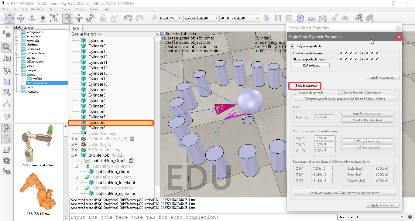
- Enabled Body is respondable and Body is dynamic .
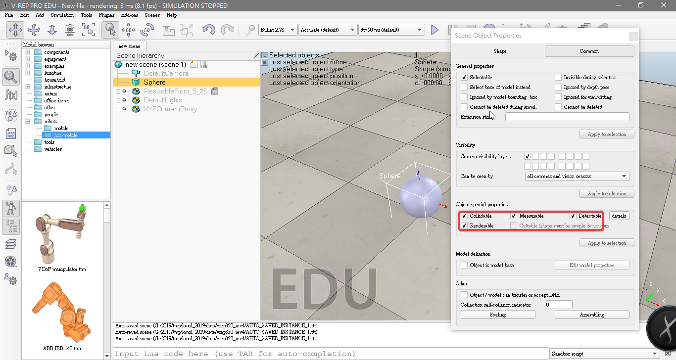
- Enable Collidable, Measurable, Renderable and Detectable in the object common properties for that shape.
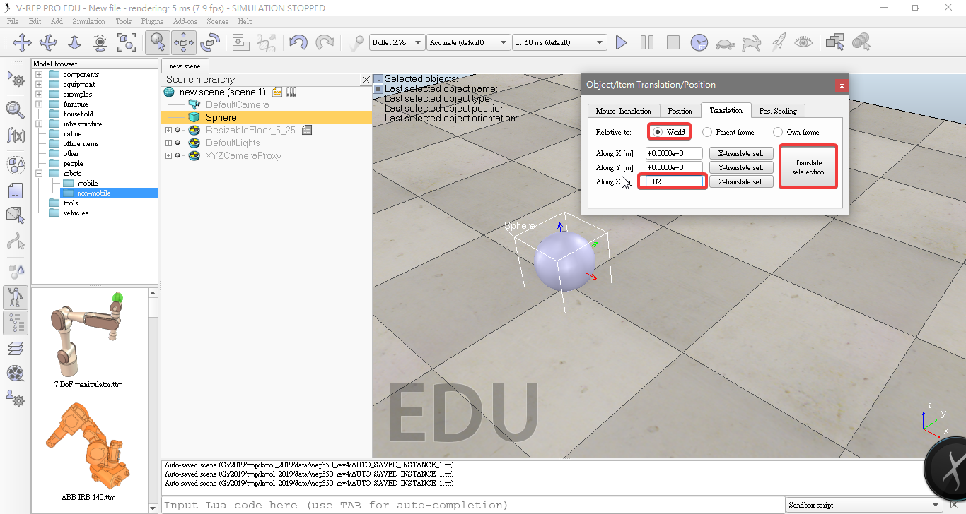
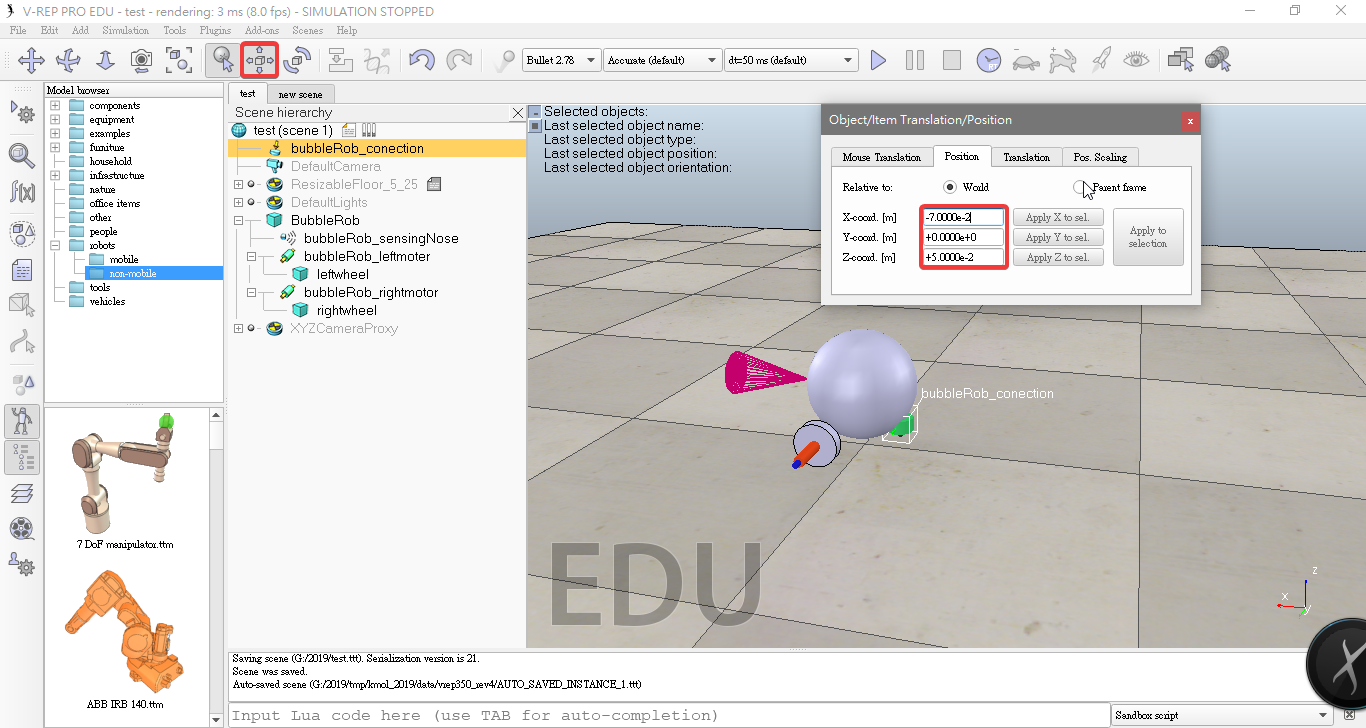
- And enter 0.02 for Along Z. We make sure that theRelative to-item is set to World. Then we click Translate selection.
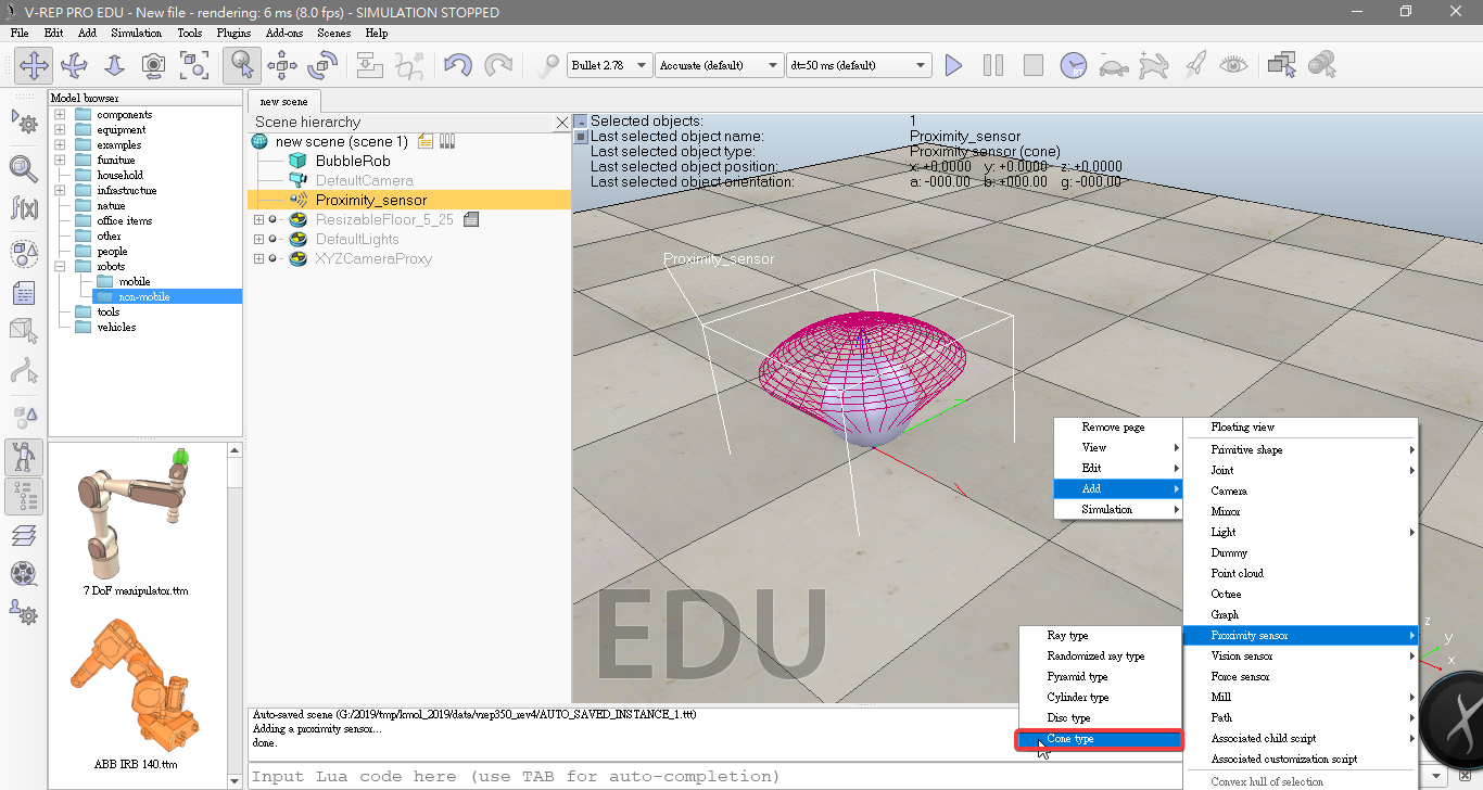
- Add a proximity sensor [Menu bar --> Add --> Proximity sensor --> Cone type]
- Rename to it bubbleRob_sensingNose
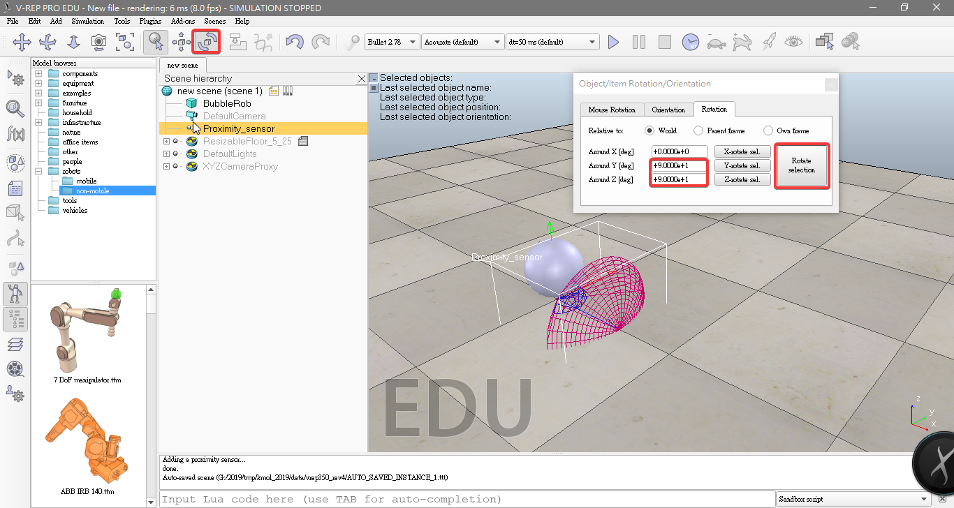
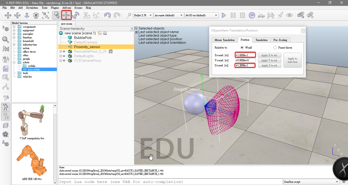
- On the orientation tab, we enter 90 for Around Y and for Around Z, then click Rotate selection.
- In the position dialog, on the positiontab, we enter 0.1 for X-coord. and 0.12 for Z-coord.
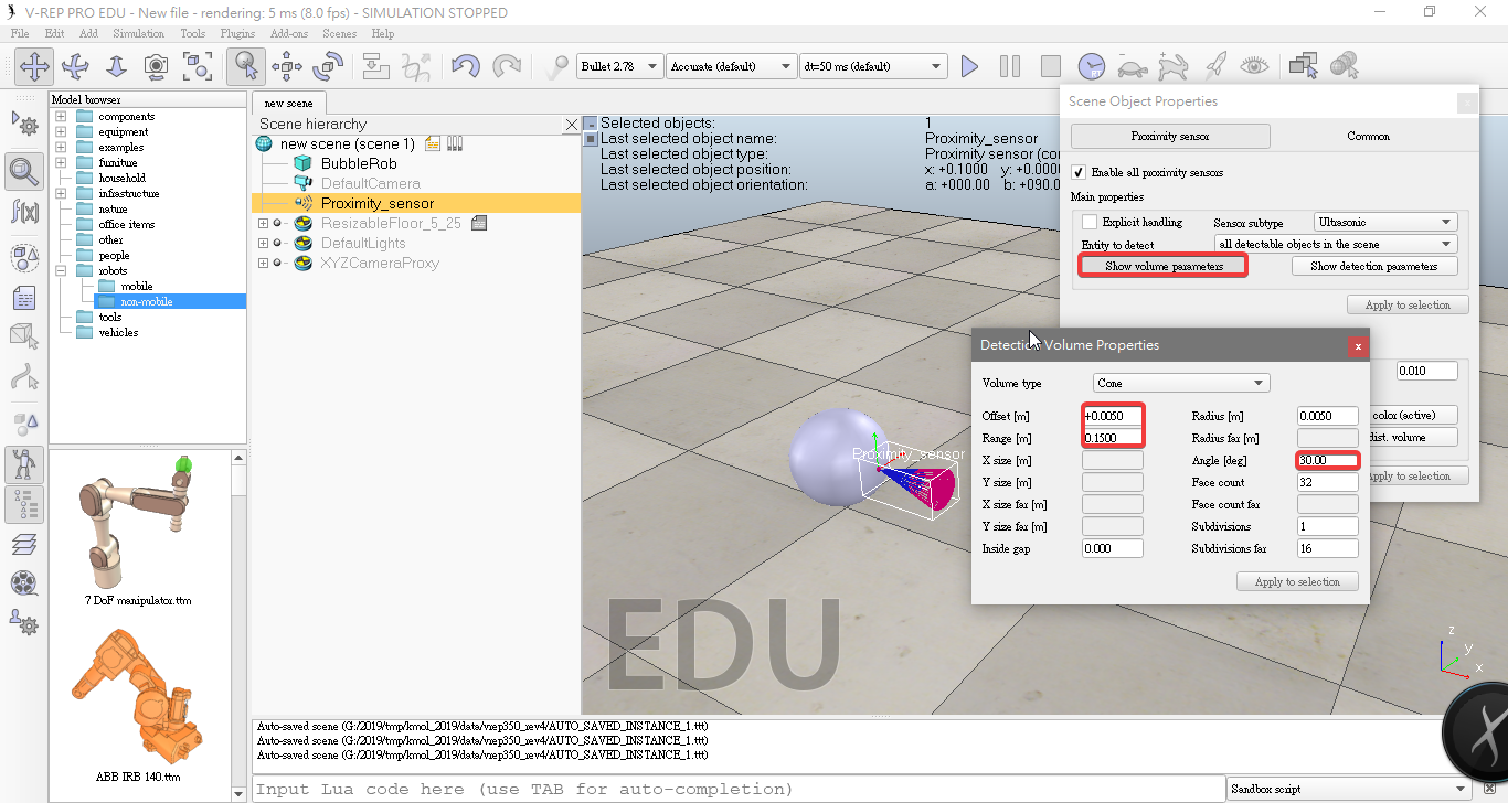
- Click Show volume parameter adjust items Offset to 0.005, Angle to 30 and Range to 0.15.
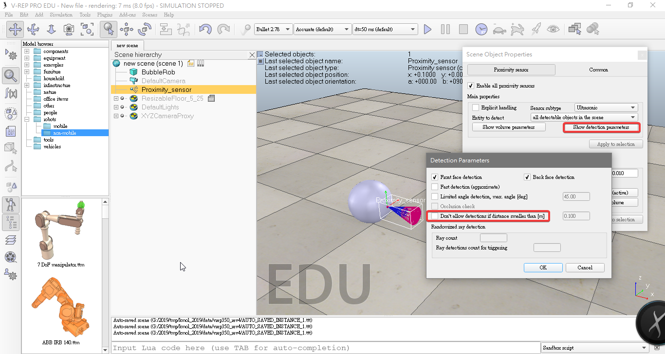
- Click Show detection parameters uncheck item Don't allow detections if distance smaller than.
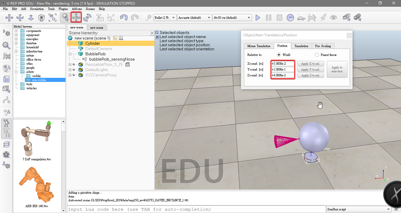
- Add a pure primitive cylinder with dimensions,size(0.08,0.08,0.02).
- Rename it to bubbleRob_leftWheel.
- Set the cylinder's absolute position to (0.05,0.1,0.04)
- Set absolute orientation to (-90,0,0).
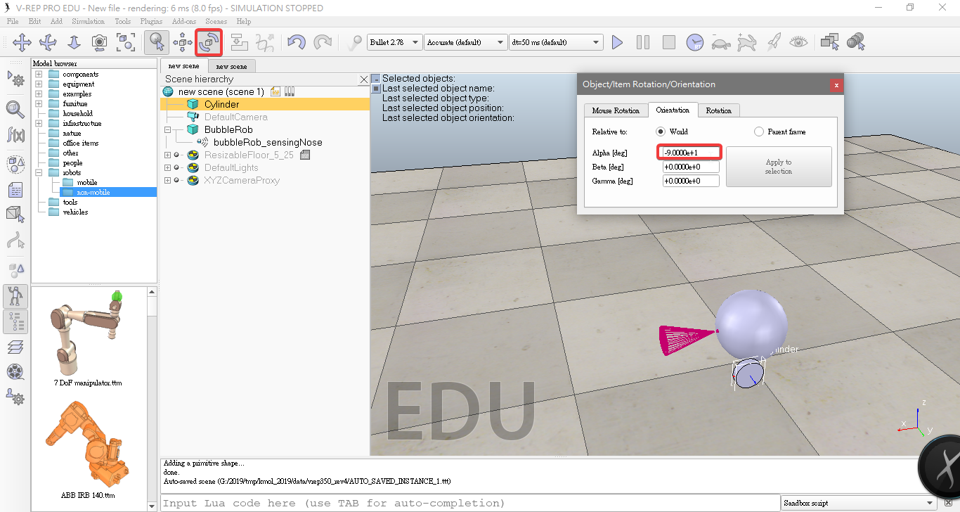
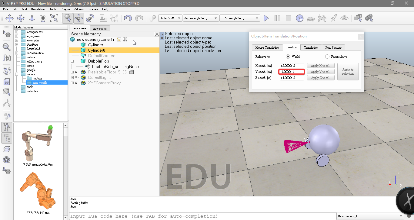
- Copy and paste the wheel, and set the absolute Y coordinate of the copy to -0.1.
- Rename it to bubbleRob_rightWheel.
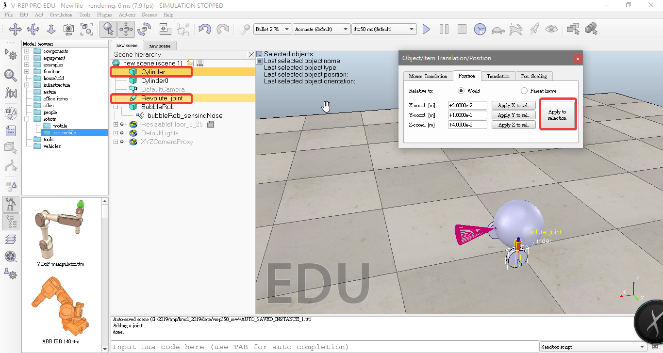
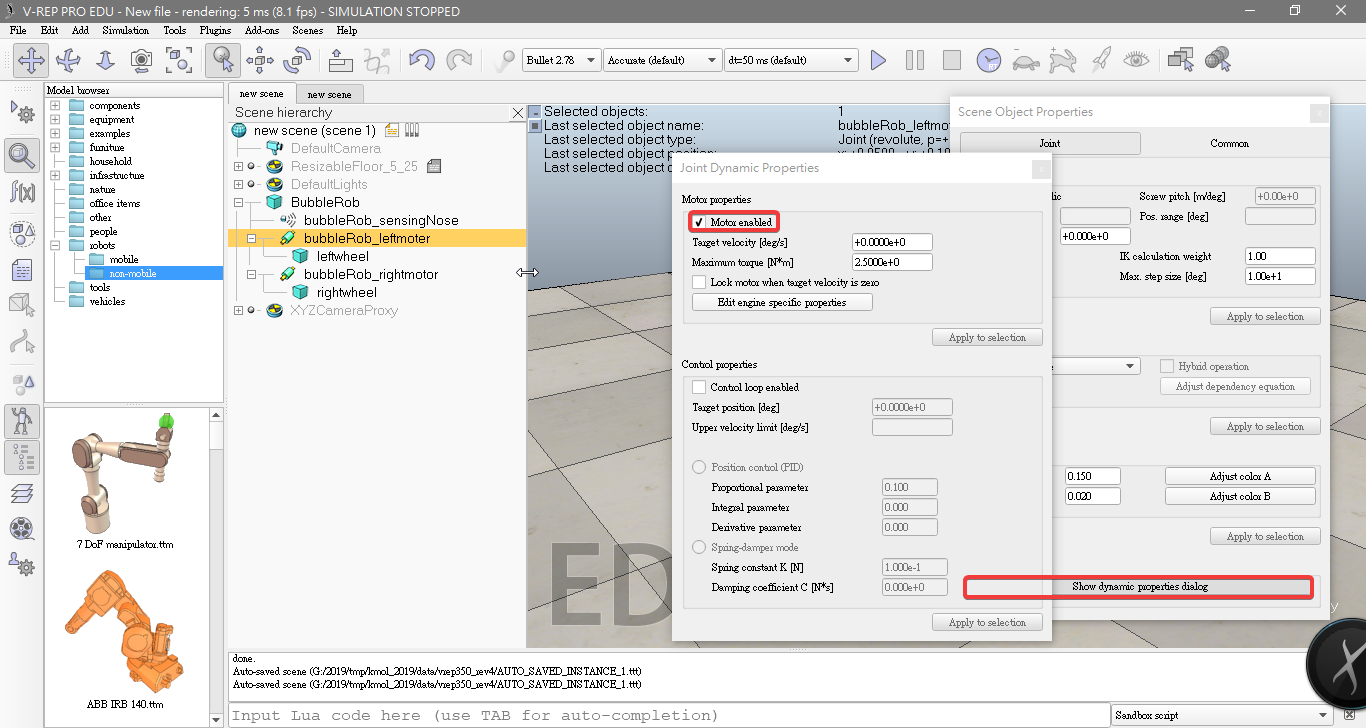
- Add joints (or motors) for the wheels. Click [Menu bar --> Add --> Joint --> Revolute]
- Rename it to bubbleRob_rightMotor.
- On the position tab, click the Apply to selection button
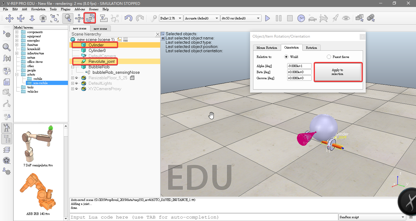
- On the orientation tab, click the Apply to selection button
- we do the same to bubbleRob_leftMotor.
- Attach the bubbleRob_sensingNose to the BubbleRob
- Attach the left wheel to the left motor ,and attach motor to BubbleRob
- Attach the right wheel to the right motor ,and attach motor to BubbleRob

- Click Show dynamic parameters to open the joint dynamics properties dialog. We enable the motor, and check item Lock motor when target velocity is zero.
- Add a pure primitive sphere with diameter 0.05 and make the sphere Collidable, Measurable, Renderable and Detectable. set absolute position to(-0.07,0,0).
- Add a force sensor object with [Menu bar --> Add --> Force sensor]. set absolute position to(-0.07,0,0.05)
- Attach the slider to the force sensor
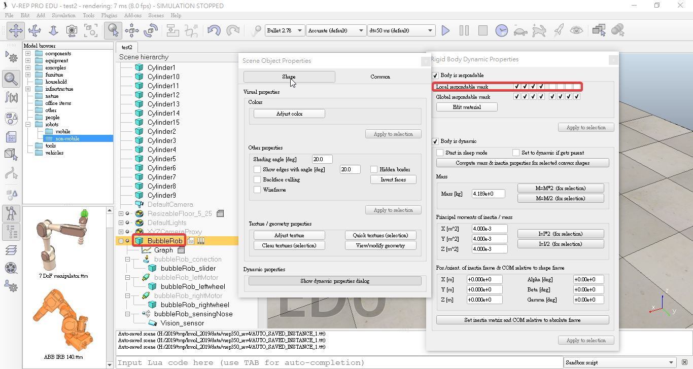
- bubbleRob set the local respondable mask to 11110000
- bubbleRob_slider set the local respondable mask to 00001111
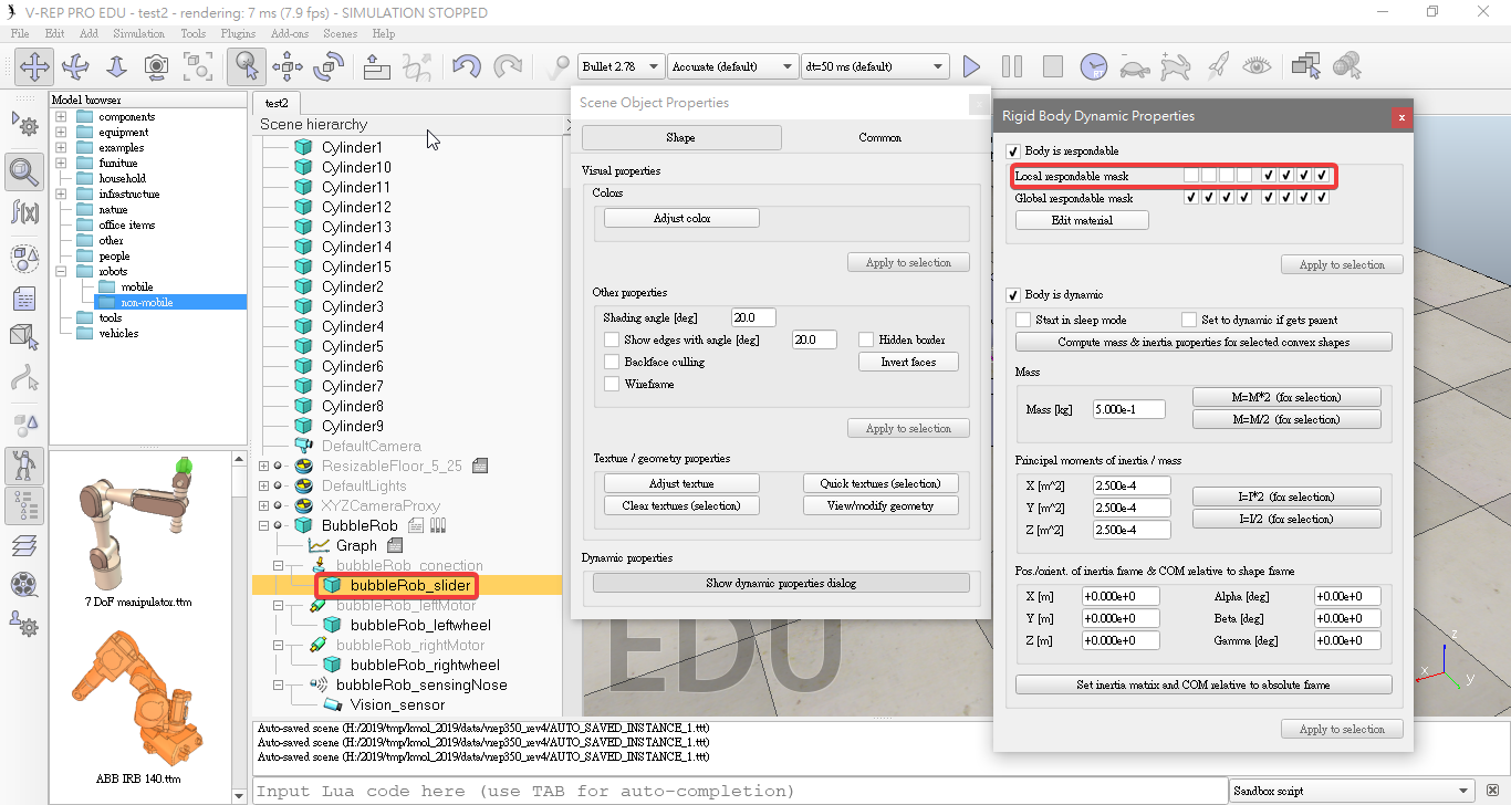
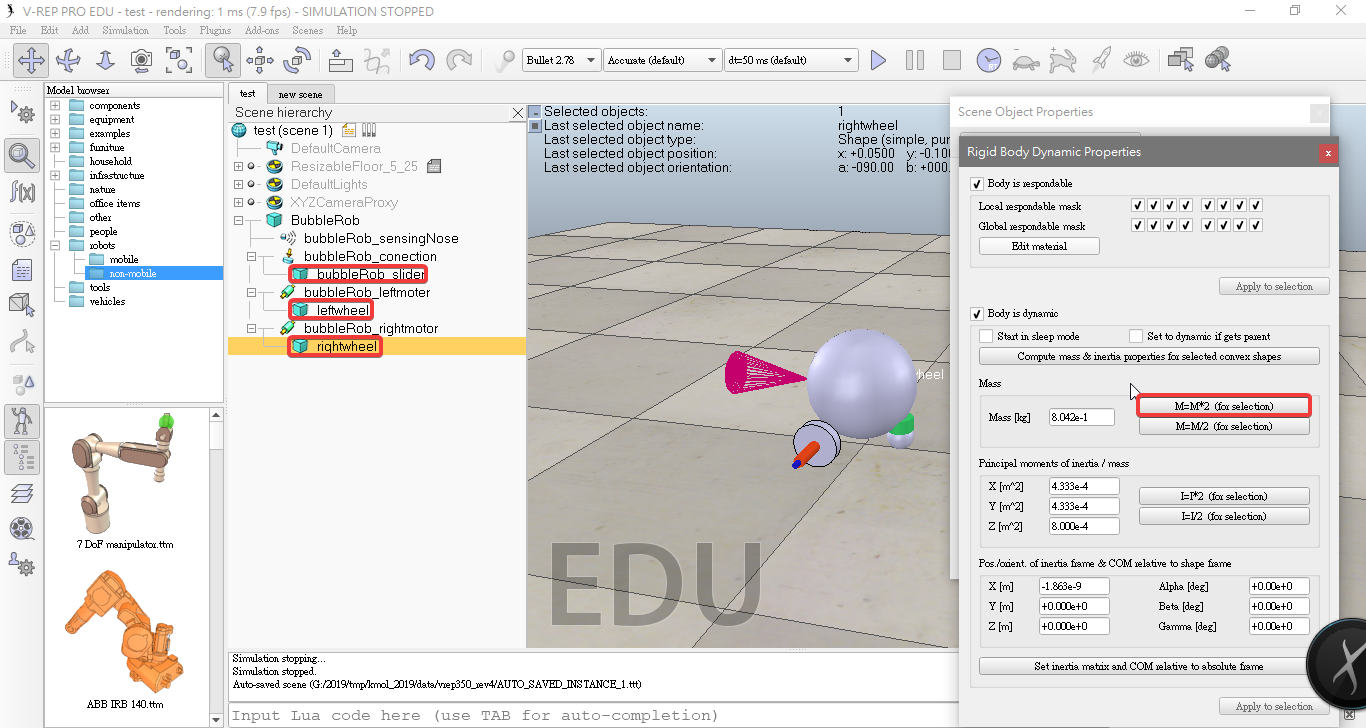
- select the two wheels and the slider, and in the shape dynamics dialog we click three times M=M*2 (for selection).
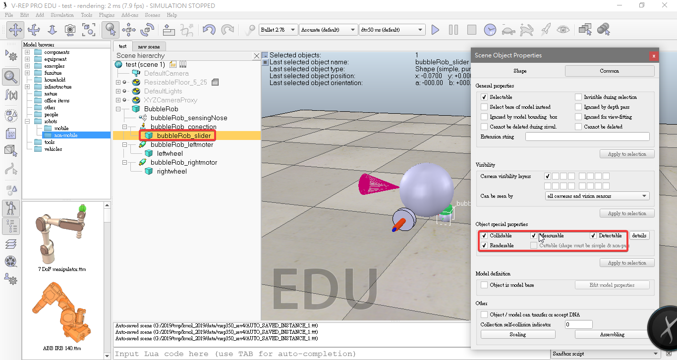
- Enabled Collidable, Measurable, Renderable and Detectable.
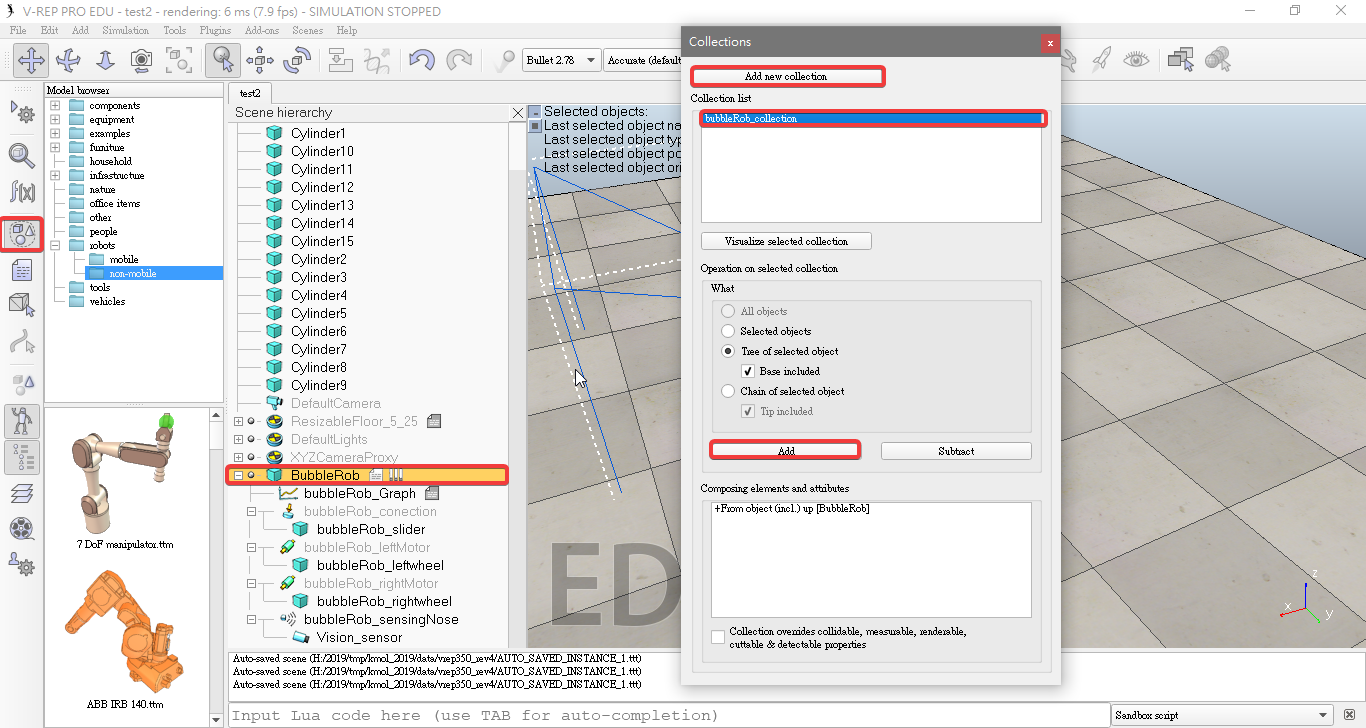
- Click Add new collection
- Select bubbleRob and then click Add in the collection dialog.
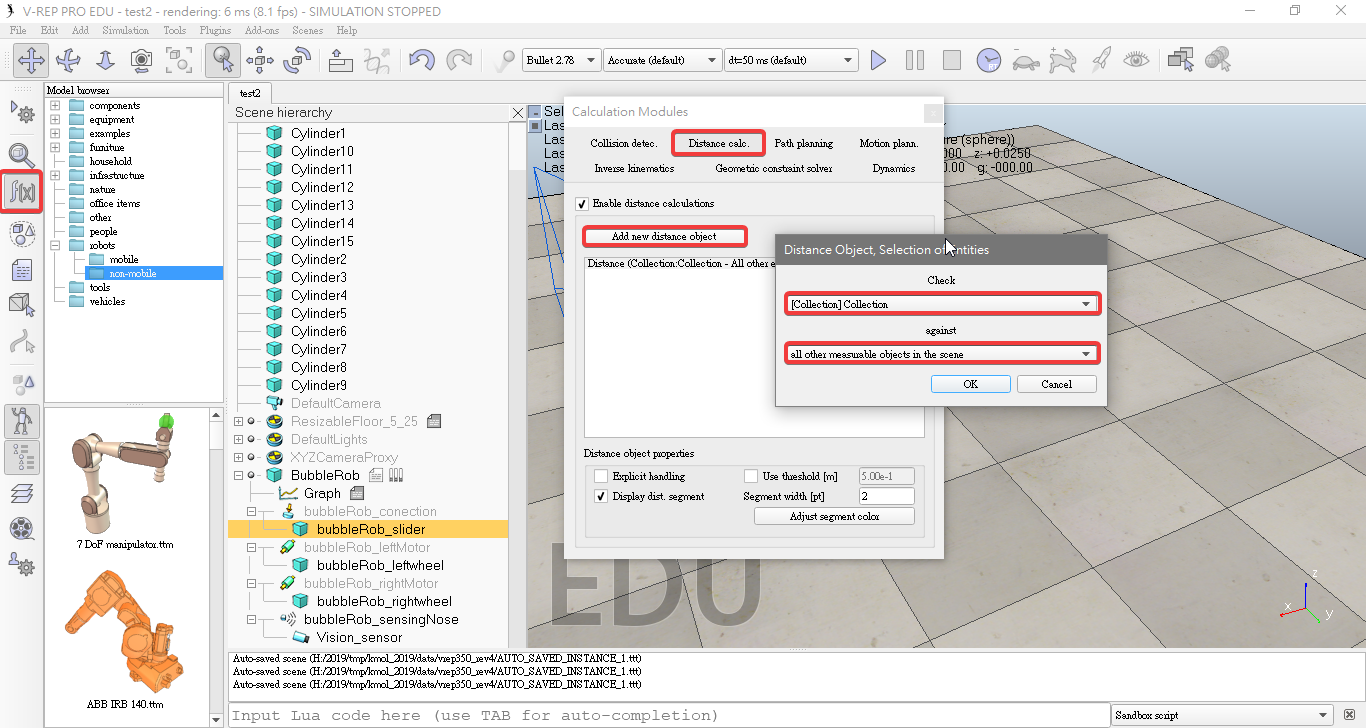
- Click Add new distance object in distance dialog.
- select a distance pair: [collection] collection - all other measurable objects in the scene.
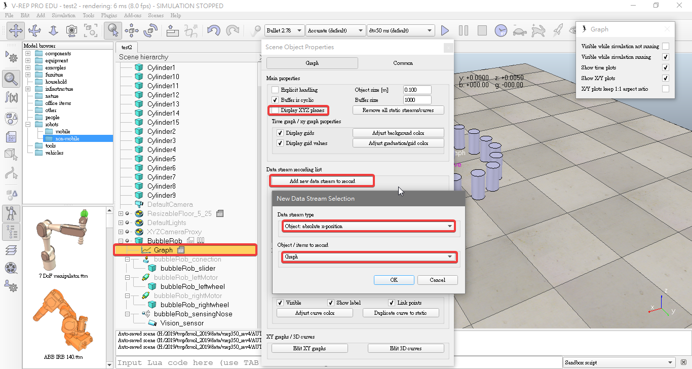
- Add a graph object Click [Menu bar --> Add --> Graph].
- Rename it to bubbleRob_graph.
- Attach the graph to bubbleRob, and set the absolute coordinates to (0,0,0.005).
- uncheck Display XYZ-planes.
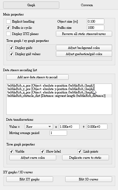
- Click Add new data stream to record
select Object: absolute x-position for the Data stream type, and graph for the Object / item to record. record the y and z positions.
select Distance: segment length for the Data stream type, and bubbleRob_distance for the Object / item to record.
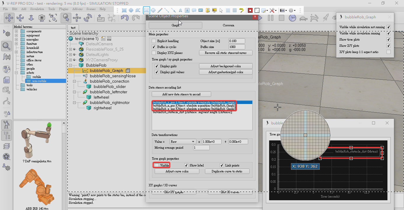
- Set x y z postion uncheck Visible.
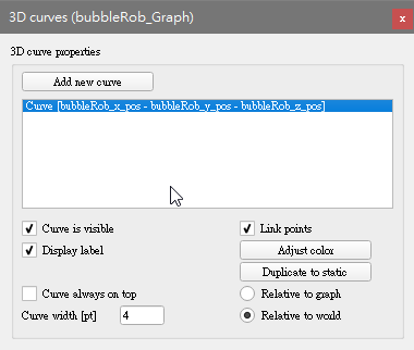
- Click Edit 3D curves, then click Add new curve.
bubbleRob_x_pos for the X-value item
bubbleRob_y_pos for the Y-value item
bubbleRob_z_pos for the Z-value item
- check the Relative to world item and set Curve width to 4.
- Add a pure primitive cylinder:(0.1, 0.1, 0.2).
- Disable Body is dynamic.
- Enable Collidable, Measurable, Renderable and Detectable.
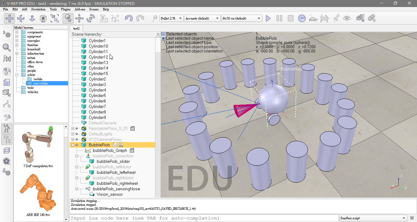
- Copy and paste the cylinder a few times, and move them to positions around BubbleRob.
- Select the model base (BubbleRob) then check items Object is model base and Object/model can transfer or accept DNA.
- Select the two joints, the proximity sensor and the graph, then enable item Igonred by model bounding box and click Apply to selection.
- Select the vision sensor, the two wheels, the slider, and the graph, then enable item Select base of model instead.
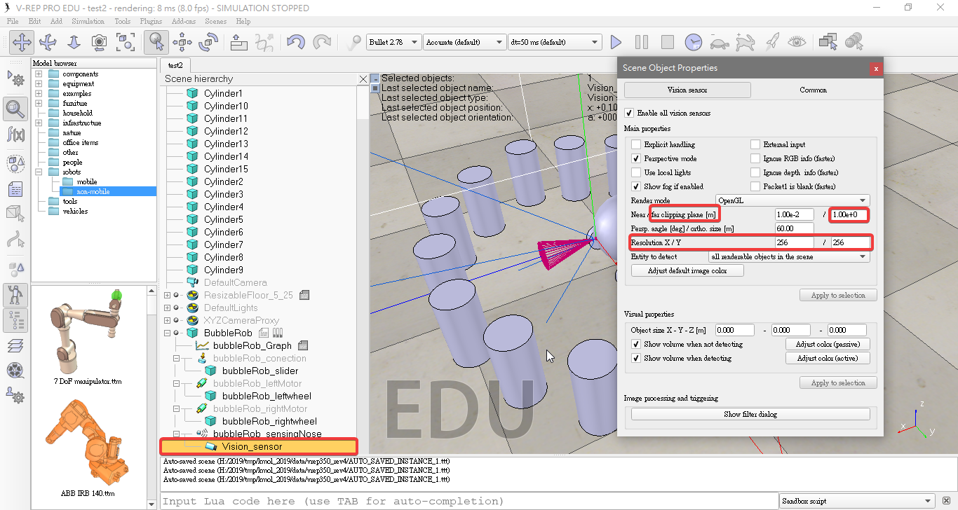
- Add a vision sensor,click [Menu bar --> Add --> Vision sensor --> Perspective type]
- At the same position and orientation as BubbleRob's proximity sensor,then attach the vision sensor to the proximity sensor.
- Set the local position and orientation of the vision sensor to (0,0,0).
- Set the Far clipping plane item to 1, and the Resolution x and Resolution y items to 256 and 256.
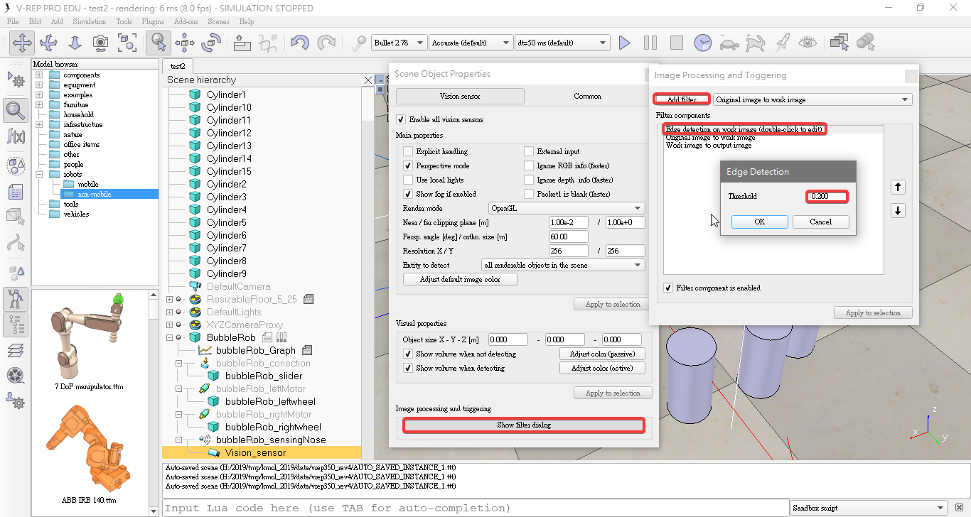
- Clicking Show filter dialog. We select the filter component Edge detection on work image and click Add filter. We position the newly added filter in second position (one position up, using the up button).
- Double-click the newly added filter component and adjust its Threshold item to 0.2.
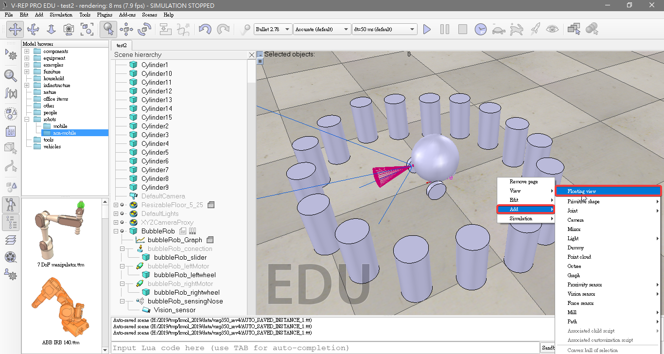
- Add a floating view
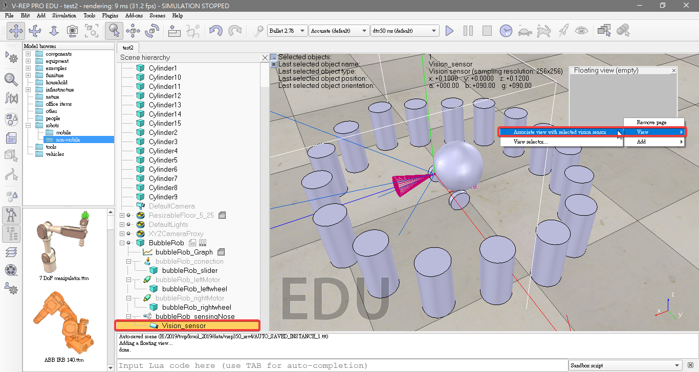
- Right-click [Popup menu --> View --> Associate view with selected vision sensor].
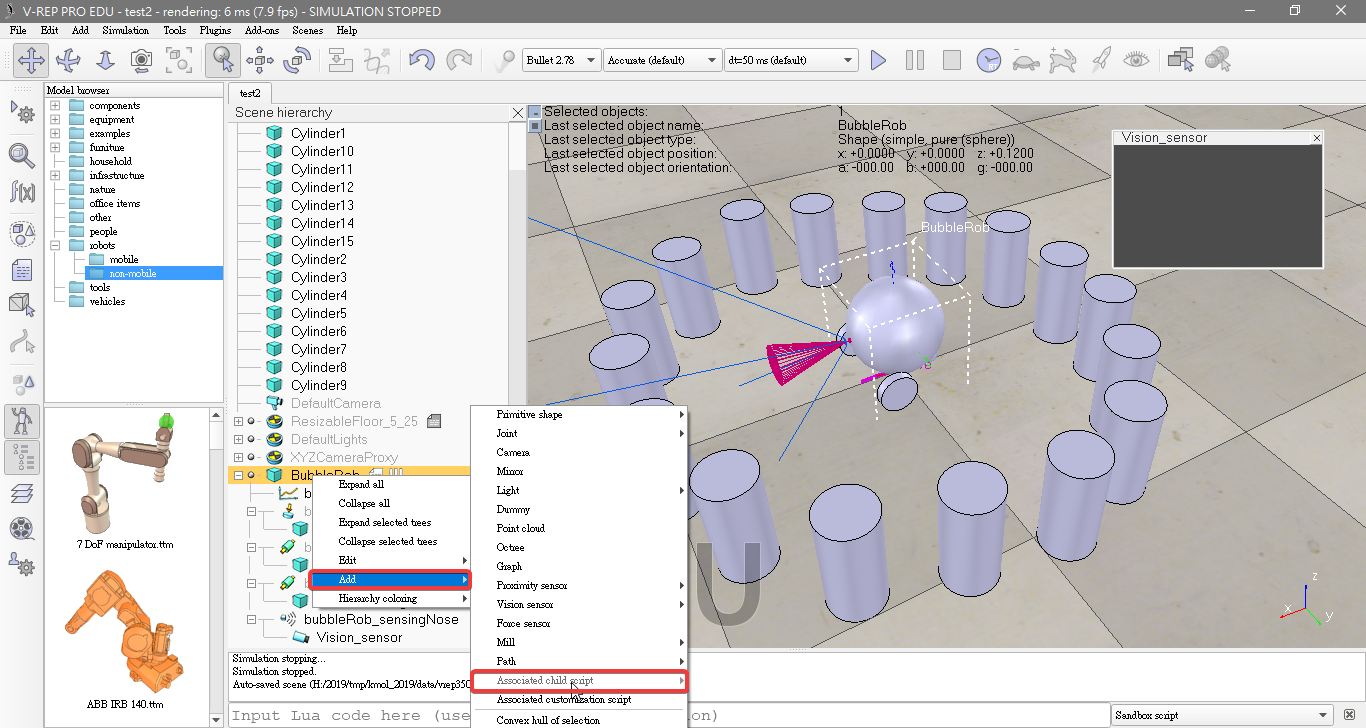
- Select bubbleRob and click [Menu bar --> Add --> Associated child script --> Non threaded].
- copy and paste following code into the script editor
function speedChange_callback(ui,id,newVal)
    speed=minMaxSpeed[1]+(minMaxSpeed[2]-minMaxSpeed[1])*newVal/100
end

function sysCall_init()
    -- This is executed exactly once, the first time this script is executed
    bubbleRobBase=sim.getObjectAssociatedWithScript(sim.handle_self) -- this is bubbleRob's handle
    leftMotor=sim.getObjectHandle("bubbleRob_leftMotor") -- Handle of the left motor
    rightMotor=sim.getObjectHandle("bubbleRob_rightMotor") -- Handle of the right motor
    noseSensor=sim.getObjectHandle("bubbleRob_sensingNose") -- Handle of the proximity sensor
    minMaxSpeed={50*math.pi/180,300*math.pi/180} -- Min and max speeds for each motor
    backUntilTime=-1 -- Tells whether bubbleRob is in forward or backward mode
    -- Create the custom UI:
        xml = '<ui title="'..sim.getObjectName(bubbleRobBase)..' speed" closeable="false" resizeable="false" activate="false">'..[[
        <hslider minimum="0" maximum="100" onchange="speedChange_callback" id="1"/>
        <label text="" style="* {margin-left: 300px;}"/>
        </ui>
        ]]
    ui=simUI.create(xml)
    speed=(minMaxSpeed[1]+minMaxSpeed[2])*0.5
    simUI.setSliderValue(ui,1,100*(speed-minMaxSpeed[1])/(minMaxSpeed[2]-minMaxSpeed[1]))
end

function sysCall_actuation()
    result=sim.readProximitySensor(noseSensor) -- Read the proximity sensor
    -- If we detected something, we set the backward mode:
    if (result>0) then backUntilTime=sim.getSimulationTime()+4 end

    if (backUntilTime<sim.getSimulationTime()) then
        -- When in forward mode, we simply move forward at the desired speed
        sim.setJointTargetVelocity(leftMotor,speed)
        sim.setJointTargetVelocity(rightMotor,speed)
    else
        -- When in backward mode, we simply backup in a curve at reduced speed
        sim.setJointTargetVelocity(leftMotor,-speed/2)
        sim.setJointTargetVelocity(rightMotor,-speed/8)
    end
end

function sysCall_cleanup()
	simUI.destroy(ui)
end
V-rep << Previous Next >> Weekly progress